Introduction
The Quebec Bridge was twenty years in the making, from the founding of the Quebec Bridge Company in 1887 to the bridge�s collapse in 1907. A cantilever bridge was proposed as the most feasible design to bridge the harsh, icy waters of the St. Lawrence River. The bridge collapsed during construction on August 29, 1907, killing eighty-six workers. Only eleven of the workers on the span were recovered alive, and some bodies were never found. A second attempt to bridge the St. Lawrence River was made. However, it also suffered a partial collapse when the middle span fell into the river. Thirteen workers were lost in the second collapse. The bridge was finally completed in 1917, and stands today. A recent review of the history of the bridge and the two collapses was written by Middleton (2001).
Conception, Design, and Construction
The St. Lawrence River was the main channel of trade for Quebec during the summer. During the winter, it filled with ice, and trade was completely cut off until the river iced over and travel was possible again across a dangerous ice bridge. The desire to bridge the St. Lawrence River was fueled by Quebec�s need to be competitive in trade. Montreal already had the Grand Trunk railway system, which passes through it from the west connecting it to Toronto. Quebec was left even farther behind when Montreal began construction in 1854 of the Victoria Bridge, which was completed in 1859, connecting it to western ports. This development quickly established Montreal as Canada�s leading eastern port. Although the need was great, the job of bridging the St. Lawrence would prove to be no easy task (pp. 7 � 8, Middleton, 2001).
The St. Lawrence River was approximately 3.2 km (2 mi.) wide at its narrowest section. Its waters were about 58 m (190 ft) deep at its middle. The velocity of the river reached 13 or 14 kph (8 or 9 mph) at times, and the tides ranged as high as 5 m (18 ft). During the winter, ice became stuck in the narrowing and piled up as high as 15 m (50 ft.) (p. 3, Middleton, 2001).
Interest in building the Quebec Bridge arose as early as 1850. However, the project did not gather momentum until 1887, when a group of businessmen and political leaders came together and formed the Quebec Bridge Committee. Due to the high level of interest in the project, the Canadian Parliament passed an act, which incorporated the committee into the Quebec Bridge Company, with a million-dollar capital and the power to issue bonds (p. 27, Middleton, 2001).
The company now faced the problem of financing the great bridge. Government funding was requested. However, no money could be awarded for the project until the bridge site was selected. With some financial help from the local Quebec legislature, preliminary surveys were made. In 1898, after years of debate, the Chaudiere site was selected from the three recommended sites to be the location of the Quebec Bridge. With a site selected, bridge design proposals poured in (p. 26, Middleton, 2001).
On June 16, 1897, the chief engineer of the Quebec Bridge Company wrote to a friend, who was also the president of the Phoenix Bridge Company (Holgate et al., 1908). In response, the Phoenix Bridge Company sent its chief engineer to meet with the Quebec Bridge Company�s chief engineer at an American Society of Civil Engineers (ASCE) meeting in Quebec in 1897. The Phoenix Bridge Company offered to prepare plans for the bridge free of charge. In return, the Quebec Bridge Company would then be obligated to give the tender for construction of the bridge to the Phoenix Bridge Company. Theodore Cooper, who learned of the Quebec Bridge project at the ASCE meeting, offered his consulting services to the Quebec Bridge Company (pp. 32 � 33, Middleton, 2001). Some of the key players in the construction and failure of the bridge are listed in Table 1.
Table 1. Key Individuals in the Design and Construction of the Quebec Bridge
Name |
Title |
| A. B. Milliken | Bridge superintendent of erection for 1st year of work |
| Benjamin A. Yenser* | General foreman of erection for remainder of project. Worked for Phoenix Bridge Company |
| Arthur H. Birks* | Resident Engineer of Erection |
| Collingwood Schreiber | Chief Engineer for Railways and Canals |
| David Reeves | President of the Phoenix Bridge Company |
| Edward Hoare | Chief Engineer for Quebec Bridge Company |
| E. R. Kinloch | Bridge erection inspector |
| John Sterling Deans | Chief Engineer for Phoenix Bridge Company |
| Norman McLure | Bridge Inspector, Civil Engineering Graduate from Princeton, hired by Cooper |
| Peter L. Szlapka | Chief Designing Engineer for Phoenix Bridge Company |
| Robert C. Douglas | Bridge engineer for Railways and Canals |
| Simon-Napoleon Parent | President of the Quebec Bridge Company |
| C. C. Schneider | Commissioned to review design work on the bridge after the collapse |
| Theodore Cooper | Consulting Engineer |
* Died in the collapse
The chief engineer of the Quebec Bridge Company, Edward Hoare, had never before worked on a bridge longer than about 90 meters (300 feet). The company decided to hire a consulting engineer, and Theodore Cooper was selected from a list of six prominent engineers for the project (Holgate et al., 1908, p. 36, Middleton, 2001). Mr. Cooper was an independent consultant operating out of New York City. He was one of the foremost American bridge builders of his day. To Mr. Cooper, this project would be the crowning achievement to his life�s work.
Petroski (1995) notes Cooper�s strong qualifications for this project. In his long career, he had written an award-winning paper pioneering the use of steel for railway bridges, and had prepared general specifications for iron and steel bridges. His method of accounting for railroad loads on bridge structures became widely used (p. 37, Middleton, 2001).
Tenders were called for on September 6, 1898 and received until March 1, 1899 (Holgate et al., 1908). They were then reviewed by Mr. Cooper. The specifications called for a cantilever structure. The basic configuration of a cantilever bridge is shown in figure 1. However, suspension bridge designs were allowed, providing they came with their own set of specifications. Earlier, noted French engineer Gustave Eiffel had considered the problem and found that a cantilever design would be superior to either a suspension or an arch bridge for the Quebec site (pp. 29 � 30, Middleton, 2001).
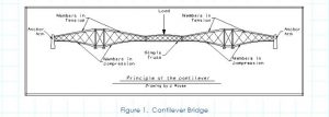
The concept of the cantilever structure was first used in 1867. William Middleton gives a clear definition of a cantilever bridge in his book: �Cantilever bridge: a bridge form based upon the cantilever principal. In its typical form cantilever arms projecting toward the center of the span from main piers are continuous with and counterbalanced by anchor arms extending between the main piers and anchor pier at each end. A simple span suspended between the two cantilever arms completes the structure. The weight of the suspended span and the cantilever arms is counterbalanced by that of the anchor arms and an anchorage embedded in the anchor pier.� (p. 175, Middleton, 2001).
Six tenders were submitted for the superstructure, and two for the substructure. After review, Theodore Cooper stated, �I hereby conclude and report that the cantilever superstructure plan of the Phoenix Bridge Company is the �best and cheapest� plan and proposal submitted to me for examination and report.� (p. 15, Holgate et al., 1908, p. 34, Middleton, 2001).
The Quebec Bridge was the longest cantilever structure ever to be attempted during its day. It would bridge the St Lawrence River approximately 14 km (9 miles) North of Quebec connecting into the Grand Trunk rail line. The cantilever arms would reach a distance of 171.5 m (562.5 ft.). They were to support a suspended span with a length of 205.7 m (675 ft.). It would stand 45.7 m (150 ft.) above the river. The initial design length clear span was 487.7 m (1,600 ft).
However, in May 1900, this span was increased to 548.6 m (1,800 ft.) by Theodore Cooper. He stated that this would eliminate the uncertainty of constructing piers in such deep water, lessen the effects of ice, and shorten the time of construction of the piers. Although there were sound engineering reasons for this change, it was also true that the lengthening of the span would also make Cooper the Chief Engineer for the longest cantilever bridge in the world (Petroski, 1995, p. 46, Middleton, 2001).
The Phoenix Company had been in correspondence with Cooper throughout this process (Holgate et al., 1908). In addition, the Quebec Bridge Company was in favor of the Phoenix Bridge Company to win the tender (Tarkov, 1986). This provides at least an impression that the process was not fair and open, even though, (Holgate et al., 1908) concluded, �As to either party influencing Mr. Cooper or causing him to modify his ideas so as to favour any tender, such a suggestion is, in our opinion, quite out of the question, and we believe that Mr. Cooper made his decisions and gave his opinions with absolute honesty.� (p. 15, Holgate et al., 1908).
Two months later the company awarded contracts to the Phoenix Bridge Company for construction of the superstructure and to the Davis Firm for construction of the substructure. However, the Phoenix Bridge Company refused to sign a contract with the Quebec Bridge Company due to the financial provisions, which left the bridge company open to considerable risk. Financial matters were finally resolved in 1903, when additional funds became available from a government grant. On June 19, 1903, a final contract was entered into between the two companies, and the name of the Quebec Bridge Company was changed to the Quebec Bridge and Railway Company (pp. 45 � 47, Middleton, 2001).
Construction of the bridge officially began on October 2, 1900, after a grand ceremony. The Quebec Bridge Company had enough funds to begin erecting the substructure. The completed piers would stand approximately 8 m (26.5 ft.) above the highest water level. The piers were made of huge granite facing stones with concrete backing. The top 5.8 m (19 ft.) of each pier was made of solid granite. The piers were tapered 1 in 12 (1 in. per foot) until they reached the dimensions of 9.1 m (30 ft.) by 40.5 m (133 ft) at the top. Each pier rested on a concrete filled caisson that was 14.9 m (49 ft) wide, 7.6 m (25 ft.) high, and 45.7 m (150 ft.) long, weighing 16.2 MN (1,600 tons) (pp. 48 � 50, Middleton, 2001).
The main vertical posts of the Quebec Bridge, once complete, would stand 96 m (315 ft.) tall and weigh approximately 3.49 MN (350 tons) (ER, 1907c). The anchor pier towers would withstand a load of 34.8 MN (3,500 tons). The tension eyebars were designed to withstand a maximum stress of 108.5 MPa (15,730 psi) and were about 12.8 m (42 ft) long (ER, 1907a). The floor system was designed to carry a live load of well over 2.79 MN (280 tons) (ER, 1907d). Due to the unprecedented size of this structure, innovative construction methods proved necessary (ER, 1907c). These considerations made the construction of the bridge a slow process.
Under a separate contract with the Quebec Bridge Company, the Phoenix Bridge Company began the construction of the approach spans in 1902 and completed them in 1903. Erection of the superstructure portion of the bridge did not begin until July 22, 1905. The Phoenix Bridge Company agreed to have the structure completed by the last day of the year in 1908. Otherwise, the company would pay $5,000 per month after this deadline to the Quebec Bridge Company until the project was finished (Holgate et al., 1908, Middleton, 2001).
vents leading up to the Collapse
As the bridge was erected, workers and supervisors found noticeable deflections in some of the chords. When the workers tried to rivet the joints between these chords, the pre-drilled holes did not line up. In addition, bends (deflections) were observed in some of the most heavily loaded compression members. Over time, some of the member deflections increased. Some of the major chords with their corresponding deflections, with the dates of measurement, are presented in table 2.
Table 2. Bridge Member Deflections
Date of Observation |
Member |
Amount of Deflection |
|
mm |
inches |
||
| June 15 | 1.5 � 6.5 | 1/16 to � | |
| June | A3R & A4R | 1.5 � 6.5 | 1/16 to � |
| June | A7R & A8R | 1.5 � 6.5 | 1/16 to � |
| June | A8R & A9R | 1.5 � 6.5 | 1/16 to � |
| June | A8L & A9L | 19 | � |
| August 6 | 7L & 8L | 19 | � |
| August | 8L & 9L | 8 | 5/16 |
| August 20 | 8R | Bent | Bent |
| August | 9R & 10R | ——- | ——- |
| August 23 | 5R & 6R | 13 | � |
| August 27 | A9L | 57 | 2 � |
Deflections were first noticed as early as mid-June, and were reported to Cooper by his on-site inspector, Norman McLure. Compression members had been cambered, so that under load the joints would line up and could be riveted together. However, some of the joints failed to close. Both men presumed that the relatively small deflections had occurred due to a pre-existing condition. They were not alarmed (p. 72, Middleton, 2001).
Subsequent inspections turned up more deflecting chords in August. Again, these were reported to Cooper on the same day that they were discovered. Cooper wired a message back referring to chords 7L and 8L, asking, �How did bend occur in both chords?� The chief engineer of the Phoenix Company replied to Cooper saying that he did not know (pp. 72 � 73, Middleton, 2001).
The chief designing engineer for the Phoenix Company, Peter Szlapka, was certain that the bend was put in the chord ribs at the shop. He later admitted that he never actually saw the chords in question. However, Norman McLure wrote, �One thing I am reasonably sure of, and that is that the bend has occurred since the chord has been under stress, and was not present when the chords were placed.� While this dispute of how the bend occurred in chords, 7L and 8L was going on, McLure reported to Cooper another occurrence of a similar bend in chords 8L and 9L (pp. 73 � 74, Middleton, 2001). The members with these deflections were the lower chords of the truss on either side of the pier � the members with the highest compressive loads under the negative moment across the pier.
A disturbing pattern was emerging. The members under the highest compressive loads were gradually buckling. These were built up with latticing, and as they deflected higher stresses were placed on the latticing as well as the rivets attaching the lattices to the main compression members.
Being dissatisfied with the theories offered by the engineers on site, Cooper developed his own theory. �None of the explanations for the bent chord stand the test of logic. I have evolved another theory, which is a possible if not the probable one. These chords have been hit by those suspended beams used during the erection, while they were being put in place or taken down. Examine if you cannot find evidence of the blow, and make inquiries of the men in charge.� McLure did as he was instructed, and reported back to Cooper that there was no evidence of such an incident (p. 74, Middleton, 2001).
Some of the engineers were unconcerned about the problem, believing that it was nothing serious. Others were still insisting that the bends were the result of a pre-existing condition. The manufacturer guaranteed that all the members had been perfectly straight when they left the yard. Another incident had occurred during the 1905 construction season, when chord A9L was dropped and bent while being handled in the storage yard. The A9L notation refers to the chord located in the anchor arm, within the ninth panel, and on the left or West side of the bridge. It was repaired and placed into the structure. Although at the time the repair was thought to be satisfactory, this member was later found to be the triggering cause of the collapse.
Cooper, although the most experienced, seemed to be the most confused by the problem. He was sixty years old at the time he accepted the position of consulting engineer for the Quebec Bridge project. He also accepted the responsibility of shop inspector of the steel fabrication and erection. His health was poor and because of this, he never visited the site once construction began on the superstructure. His consulting services were based on the information that was reported to him by others in charge. Cooper�s official eyes and ears on the construction site was Norman McLure, a young civil engineer who had been appointed by Cooper himself. Cooper was also very poorly compensated for his work (Petroski, 1995, Middleton, 2001).
McLure continued to argue that the bends in the members had occurred after they were installed. Some of the workers had observed the deflecting chords and were concerned enough to not report to work for a few days. However, when McLure and Cooper disagreed on the cause of the deflections, McLure did not have the confidence to contradict Cooper. Work continued on the bridge. There had already been a three-day strike over working conditions, and the workers who had not agreed with the new terms had left. This greatly reduced the number of workers on the project, and there was concern that a temporary stoppage would cause more workers to leave and delay the project.
After another routine inspection, chord A9L was placed under observation when its initial deflection of 19 mm (��) had increased to 57 mm (2 ��) in less than two weeks. The opposite chord A9R was bent in the same direction. There was growing concern about the deflections. One of the construction foremen decided to halt work on the bridge until matters could be resolved. On August 27, the same day construction was halted; McLure sent a message to Cooper informing him that construction would not resume until he reviewed the matter. The next day, McLure went to New York to seek advice from Cooper (pp. 78 � 79, Middleton, 2001).
The erection foreman that had ordered the work to stop changed his mind, and with reassurance from Edward Hoare, the chief engineer of the Quebec Bridge Company, work began again that day. The only reason given for this decision was in a note from Hoare to Cooper stating, �the moral effect of holding up the work would be very bad on all concerned and might also stop the work for this season on account of losing the men.� Two days later, news of the matter reached the Phoenixville office and the project superiors there met and discussed the problem. They relayed a message back by telephone, saying that it was safe to resume work on the bridge. They had somehow reached the conclusion that the bends in the chords had occurred before they left the yard. The Phoenix Company�s chief engineer had stated that the chord members were carrying �much less than maximum load.�
In the meantime, McLure was meeting with Cooper in New York. Neither of the men was aware that construction had resumed on the bridge. After a brief discussion between the two men on August 29, Cooper wired the Phoenixville office saying, �Add no more load to the bridge until after due consideration of facts. McLure will be over at five o�clock.� Cooper�s reasoning for informing the Phoenixville office rather than directly relaying it to the site, was that he felt that action would be taken faster if the information went to the site through Phoenixville. McLure had assured Cooper that he would wire the information to the site on his way to the Phoenixville office. In his haste to get to his destination, he neglected to send the information.
The message from Cooper reached the Phoenixville office at 1:15 p.m. It was ignored in the absence of the chief engineer. At around 3:00 p.m. Phoenixville�s chief engineer returned to his office. After seeing the message, he arranged for a group meeting as soon as McLure arrived. McLure arrived at roughly 5:15 p.m. and the men discussed the circumstances briefly before deciding to wait until the next morning to decide a course of action (pp. 78 � 80, Middleton, 2001).
Collapse
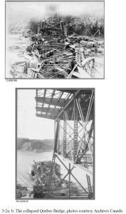
Meanwhile, back at the construction site, at about the same time the decision-makers in Phoenixville were ending their meeting, the Quebec Bridge collapsed at 5:30 p.m. The thunderous roar of the collapse was heard ten km (six miles) away in Quebec (p.80, Middleton, 2001). The entire south half of the bridge, approximately 189 MN (19,000 tons) of steel, fell into the waters of the St. Lawrence within 15 seconds. Eighty-six workers were present on the bridge at the time. Only eleven workers on the span survived.
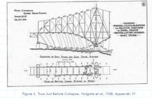
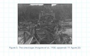
The A9L bottom compression chord, which was already bent, gave way under the increasing weight of the bridge (figure 2). The load transferred to the opposite A9R chord that also buckled. The piers were the only part of the structure that survived. The wreckage is shown in figure 3. Of 38 Caughnawaga Mohawk ironworkers who had left their village to work on the bridge, 33 were killed and two were injured (p. 84, Middleton, 2001).
The Royal Commission Report
The Governor General of Canada formed a Royal Commission, comprised of three civil engineers, whose sole task was to investigate the cause of the collapse. They were Henry Holgate, of Montreal, John George Gale Kerry of Campbellford, Ontario, and John Galbraith of Toronto. Their completed report was a pioneering event in the discipline of forensic engineering, and consisted of over two hundred pages plus twenty-one appendices. As stated by (Middleton 2001, p. 91), ��the thoroughness and objectivity of their inquiry and report stand even today as models of their kind.�
The immediate cause of failure was found to be the buckling of compression chords A9L and A9R. The official report attributed the collapse to a number of reasons. Listed below are some of the major findings (pp. 9 � 10, Holgate et al., 1908):
- �The collapse of the Quebec Bridge resulted from the failure of the lower chords in the anchor arm near the main pier. The failure of these chords was due to their defective design.�
- �We do not consider that the specifications for the work were satisfactory or sufficient, the unit stresses in particular being higher than any established by past practice. The specifications were accepted without protest by all interested.�
- �A grave error was made in assuming the dead load for the calculations at too low a value and not afterwards revising this assumption. This error was of sufficient magnitude to have required the condemnation of the bridge, even if the details of the lower chords had been of sufficient strength, because, if the bridge had been completed as designed, the actual stresses would have been considerably greater than those permitted by the specifications. This erroneous assumption was made by Mr. Szlapka and accepted by Mr. Cooper, and tended to hasten the disaster. �
- �The loss of life on August 29, 1907, might have been prevented by the exercise of better judgement on the part of those in responsible charge of the work for the Quebec Bridge and Railway Company and for the Phoenix Bridge Company.�
- �The failure on the part of the Quebec Bridge and Railway Company to appoint an experienced bridge engineer to the position of chief engineer was a mistake. This resulted in a loose and inefficient supervision of all parts of the work on the part of the Quebec Bridge and Railway Company.�
- �The work done by the Phoenix Bridge Company in making the detail drawings and in planning and carrying out the erection, and by the Phoenix Iron Company in fabricating the material was good, and the steel used was of good quality. The serious defects were fundamental errors in design.�
- �The professional knowledge of the present day concerning the action of steel columns under load is not sufficient to enable engineers to economically design such structures as the Quebec bridge. A bridge of the adopted span that will unquestionably be safe can be built, but in the present state of professional knowledge a considerably larger amount of metal would have to be used than might be required if our knowledge were more exact.�
Causes of Failure
The fall of this massive bridge can be traced back to several technical factors. The top and bottom chords for the anchor and cantilever arms of a bridge were typically designed as straight members. This common practice made the fabrication of these members easier. The top chords for the anchor and cantilever arms in the Quebec Bridge were slightly curved, for aesthetic reasons. This added difficulty to the fabrication of such unusually large members. The curvature also increased the secondary stresses on the members, reducing their buckling capacity. According to Engineering Record, �As a rule secondary stresses are much more dangerous in tension that in compression members, which seem to have been the first to give way in the Quebec bridge� (ER, 1907e).
Another concern during the erection of the bridge was the joints. The ends of all the chords were cambered to allow for the small deflections that were expected to occur when the chords came under their full dead load. These butt splices were bolted to allow for movement. The splices initially touched only at one end, and could not fully transfer their load until they had deflected enough to cause full contact at the splices. At this point, they were permanently riveted in place. The result was to be a rigid joint that transferred loads uniformly across its area to ensure only axial loading. Great care had to be taken while working around these joints until they were riveted (pp. 70 � 72, Middleton, 2001).
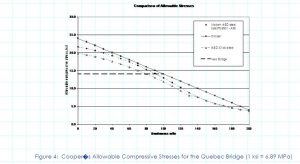
Adding to the design problems, Cooper increased the original allowable stresses for the bridge. He allowed 145 MPa (21 ksi) for normal loading and 165 MPa (24 ksi) under extreme loading conditions. These were questioned by the bridge engineer for the Railways and Canals as being unusually high. The new units stresses were accepted anyway based solely on Cooper�s reputation (Holgate, et al., 1908).
Cooper developed an allowable compressive stress formula (developed in psi) based on the slenderness ratio (l/r) of the member:
Allowable compressive stress = 165 � 0.69 (l/r) MPa = 24,000 � 100 (l/r) psi (1)
Where l = length of compression member,
r = radius of gyration =
I = moment of inertia, and
A = cross-sectional area.
Cooper�s formula is compared to contemporary allowable stresses from the American Institute of Steel Construction (AISC, 1989) as well as the 96.5 MPa (14 ksi) allowable stress adopted for the second bridge (p. 107, Middleton, 2001) in figure 4. AISC curves are shown for both 230 MPa (33 ksi) and 250 MPa (36 ksi) steel. Cooper�s stresses are higher than those in use today by 3.3 to 8.7 % over a range of slenderness ratios from 10 to 100. Given the lower and uncertain quality of the materials available to Cooper, along with the less developed state of knowledge of compression members at that time, Cooper�s formula clearly represents an unsafe practice.
The Quebec Bridge was an enormous structure, and very little was known as to how it would behave mechanically. The Quebec Bridge Company lacked funding to adequately perform testing. Cooper had required extensive tests on the eyebars. The eyebars formed major tension members in the top chords. He did not require the compression members to be tested. Later, Cooper would state the reason for this as being, �There is no machine or method existing by which any such test could be made� (p. 56, Middleton, 2001). However, when the company did finally secure funds for testing, Cooper rejected the idea stating that too much time had been wasted already.
Another oversight was that the stresses were not recalculated once Cooper increased the span from 487.7 m (1,600 ft) to 548.6 m (1,800 ft). The stress calculations were based on the 487.7 m (1,600 ft) span dimension. Once this error had been discovered and brought to Cooper�s attention, he immediately made an estimate of the new stresses that would occur. He found that they would be approximately 7 percent more. Weights were then recalculated from the new information. They were found to be as much as 10 percent in excess of those previously calculated (p. 65, Middleton, 2001). The initial design weight for the bridge was expected to be 276 MN (62 million pounds). The real weight of the bridge was estimated at 325 MN (73 million pounds) (Tarkov, 1986).
In the rush following the final financial arrangements of 1903, the necessity of revising the assumed weights was overlooked both by the engineers of the Phoenix Bridge Company and by those of the Quebec Bridge Company, with the result that the bridge members would have been considerably over-stressed after completion. �This error was sufficient to have condemned the bridge had it not fallen owing to other causes.� (p. 37, Holgate et al., 1908).
Table 3, based on the Royal Commission Report, compares the actual and assumed dead loads. �The difference between these two sets of concentrations indicate a fundamental error in the calculations for the bridge. In a properly computed bridge the assumed dead load concentrations upon which the make-up of the members is based should agree closely with the weight computed from the dimensions in the finished design and with actual weights� (Holgate et al., 1908).
Table 3. Comparison of Assumed and Actual Dead Load
Element |
Assumed Dead Load |
Actual Dead Load |
Difference |
||
kN |
lb. |
kN |
lb. |
Percent |
|
| Half suspended span | 21,538 | 4,842,000 | 25,328 | 5,694,000 | 17.6 |
| Cantilever arm | 58,740 | 13,205,200 | 70,300 | 15,804,000 | 19.7 |
| Anchor arm | 59,240 | 13,317,600 | 77,034 | 17,318,000 | 30.0 |
At the time this error was discovered, a large portion of the fabrication had been completed and a considerable amount of bridge erection was finished. Cooper accepted these heavier loads and stresses, in addition to the already high stresses set for the bridge, as being within acceptable limits. His only other alternatives were to start over, strengthen the bridge in place, or abandon the project.
Procedural and Professional Aspects
Cooper insisted on retaining full control of the project, even at a considerable distance. Schreiber recommended that the governmental agency of Railways and Canals hire a consultant on their behalf. This engineer would, in a sense, be double-checking Cooper�s work and ultimately have the final authority. After finding out this news, Cooper, the Quebec Bridge Company, and the Phoenix Bridge Company immediately objected. In a letter to Edward Hoare, Cooper wrote, �This puts me in the position of a subordinate, which I cannot accept.� (p. 52, Middleton, 2001). Cooper met with Schreiber personally. Following this meeting, Schreiber revised his recommendation to eliminate the need to hire an additional project consultant. The new amended order-in-council to the Railways and Canals gave an unclear definition of just how much authority Cooper would have over the project.
According to Middleton (p. 53, 2001), �While there remained a requirement to submit all plans for the approval of the chief engineer of Railways and Canals, it was treated as a perfunctory formality. When later modifications to the specifications appeared desirable, Cooper made them without reference to the government engineers, and there was no evidence that Schreiber ever questioned a decision made by Cooper or interfered in any way with the work.� This opinion is supported by a statement in a letter from Deans to Cooper. In it he wrote, �The suggested action by Mr. Schreiber would place the business in a much worse condition than it was originally in.� He also wrote, �� it is simply being necessary to have Schreiber�s signature as a matter of form.� To further these implications, in a another letter from Deans to Cooper, he wrote, �I have written him again, (Schreiber) and urged him to stop entirely this proposed plan, and explaining that the sole purpose of the order in council was to give you the final authority to settle all details, the government approval being a mere formality, and in this way save time which was so valuable� (Holgate et al., 1908).
No clear chain of command existed. It was assumed that the final authority rested with Theodore Cooper. All concerns were directed towards him, even though, due to illness, he was unable to travel to the job site. There was no one present on the job site that was qualified to oversee this type of work or who was in a position to make a decision. Whenever the need arose, the authorities on site would confer with each other before making any decision. In the few occasions where some decision had been reached, there was hesitation in carrying it out. The authors of the Royal Commission Report wrote, �It was clear that on that day the greatest bridge in the world was being built without there being a single man within reach who by experience, knowledge and ability was competent to deal with the crisis� (Holgate et al., 1908).
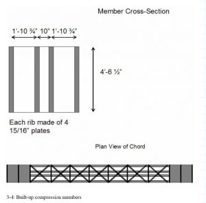
Capacity of Compression Members
The commission had suspected that the A9L compression chord failed due to improper latticing. Compression tests were performed on one-third scale models of the compression chords in November 1907 and January 1908 to verify this theory. The compression chord members for the Quebec Bridge consisted of four multi-layered ribs (figure 5). They were stiffened by the use of diagonal latticing to make them act as one unit. During testing, the lattice system failed explosively due to shearing of its rivets, immediately followed by buckling of the chord. This confirmed the commission�s findings that the chords were inadequately designed. In Schneider�s opinion, �These members consist of four separate ribs, not particularly well developed as compression members, and their connections to each other are not of sufficient strength to make them act as a unit� (p. 97, Middleton, 2001). Schneider wrote in his report, which was published as an appendix to the Royal Commission Report, �If a column is made up of several shapes or parts, they have to be connected in such a manner that they will act as a unit. In an ideal column each part would take its share of the load and no connection would be required. In practice, however, as stated before, bending will occur before the buckling load is reached, causing shearing strains which have to be transferred through the connections, as latticing, tie plates or cover plates. These connection parts have, therefore, to perform the same function as the web of a girder or the web system of a truss� (Holgate et al., 1908).
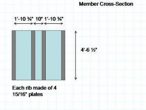
Figure 5: The Built-up Compression Members (1 ft. = 305 mm, 1 in. = 25.4 mm)
This unprecedented large scale testing and studying of compression members and their connections led to major advancements in the field of engineering. Bridge specifications were improved after this collapse (Shepherd and Frost, 1995). Another advancement was the formation of two organizations, the American Institute for Steel Construction in 1921, and the American Association of State Highway and Transportation Officials in 1914. These organizations advanced the field of engineering by providing the means to fund research, which had become too difficult and expensive for fabricating companies to conduct on their own (Roddis, 1993).
Ethical Aspects
Several ethical concerns can be pointed out in this case. The major one is that deformations went unheeded for so long. The engineers on site argued among themselves as to the cause. Although the workers who failed to report to work because of the deformations lacked the technical expertise, they seemed to be the only ones who properly understood what was really happening to the bridge (p. 78, Middleton, 2001). Engineers and others in charge must be open minded to the ideas of the laborers, many of which have years of hands on experience.
Another ethical concern was Cooper�s rejection to having an independent engineer check his work. His decisions were not questioned, even when they seemed to be unusual. An independent consultant may have not allowed the higher than normal design stresses. Some of the other errors such as the underestimated dead loads and the failure to recheck the weight could have been discovered before the bridge collapsed. In conclusion of this thought, �Cooper�s engineering expertise became the sole factor that was relied upon for assuring structural integrity of the bridge.� (Roddis, 1993).
Aftermath
The lives of those involved with the Quebec Bridge, from the designers to the construction workers, were forever changed after the accident. None however, was affected as much as the families of the ones who died and Theodore Cooper. Edward Hoare went to work for the National Transcontinental Railway Commission. John Deans continued to serve as chief engineer of the Phoenix Bridge Company. He eventually became vice president of the company. Szlapka continued his duties as chief designer for the Phoenix Company. Cooper withdrew from practice to live out a lonely retirement. Ironically, he died only two days after the Prince of Wales officially dedicated the completed Quebec Bridge (Middleton, 2001).
The Second Bridge
After the collapse, the government took over the design and construction of the new bridge. This also provided the financial support for the project. The second bridge was substantially heavier than the first. Petroski (1995) compares dimensions of the two bridges, showing the dramatic increase in member sizes. The cross sectional area of the critical compression member for the old bridge had been 543,000 mm2 (842 in.2), whereas that of the new bridge was 1,250,000 mm2 (1,941 in.2) (p. 113, Petroski, 1995, p. 116, Middleton, 2001).
The second attempt to bridge the St. Lawrence was not without problems. The project suffered a second collapse in 1916, when a casting in the lifting apparatus broke, causing the center span to fall into the water. Thirteen workers lost their lives in this accident. The 50 MN (5,000 ton) span sank to the bottom of the river to rest beside the wreckage of the first bridge, which still remains there today. The second bridge was finally completed in 1917 and weighed two and a half times as much as the first one (Tarkov, 1986).
Conclusions
At Quebec, the greatest bridge in the world was under construction in 1907 under severe financial constraints, with inadequate funds provided for either engineering work or the bridge itself. These constraints had delayed engineering analysis and led to adoption of unconservative specifications. When the miscalculation of the dead load was identified, the measures taken to re-analyze the structure were not adequate. On this project, virtually every conflict between safety and economy was resolved in favor of economy. Most of the poor engineering decisions were made by the prominent consulting engineer, Theodore Cooper.
Cooper�s reluctance to travel to the site, based on his poor health, led to confusion about responsibility and site supervision. When skilled ironworkers observed the growing deflections, indicating a gradual collapse of the structure, a confident site supervisor might have realized the gravity of the situation and halted construction. However, the engineers on the site lacked the confidence and the authority to contradict Cooper�s judgments.
The Royal Commission Report, which investigated the collapse and identified the engineering and procedural errors that had lead to it, remains a pioneering document in the field of forensic engineering. The lessons learned from the case had many important impacts on the engineering profession, particularly in Canada and the U.S.
Acknowledgements
Support for this research was provided by the National Science Foundation under the project �Developing Case Studies in Failures and Ethics for Engineering Educators,� project number DUE 0127419.
References
American Institute of Steel Construction (AISC) (1989), Manual of Steel Construction, Allowable Stress Design, Ninth Edition, Chicago, Illinois.
Engineering Record (ER). (1907a). �The Anchor Pier Towers of the Quebec Bridge� (1907), Engineering Record, Vol. 55, January 12, pgs. 34-35.
Engineering Record (ER). (1907b). �Erection Attachments for Bottom Chords and Vertical Posts of the Quebec Bridge,� (1907), The Engineering record, building record and the sanitary engineer. Vol. 55, January 19, 1907.
Engineering Record (ER). (1907c). �Erection of the Main Vertical Posts of Quebec Bridge�, (1907), Engineering Record, Vol. 55, January 26, pgs. 92-94.
Engineering Record (ER). (1907d). �The Quebec Bridge Superstructure Details, Part VIII,� (1907), The Engineering record, building record and the sanitary engineer. August 17, 1907.
Engineering Record (ER). (1907e). �The Cause of the Quebec Bridge Failure�, (1907), Engineering Record, Vol. 56, Sept. 14, pg. 276, Sept. 21, pg. 302.
Holgate, Henry; Derry, John, G. G.; Galbraith, John. (1908). Royal Commission Quebec Bridge Inquiry Report. Sessional Paper No 154. S.E. Dawson printer to the King Ottawa.
Middleton, William D. (2001). Bridge at Quebec. Indiana University Press, Indiana, USA.
Petroski, Henry (1995). Engineers of Dreams: Great Bridge Builders and the Spanning of America, Knopf, New York.
Roddis, W. M. Kim (1993). �Structural failures and engineering ethics.� Journal of Structural Engineering. 119(5), 1539-1555.
Shepherd, Robin and Frost, J. David (1995). Failures in Civil Engineering, Structural, Foundation and Geoenvironmental Case Studies. American Society of Civil Engineers, New York, New York.
Tarkov, J. A. (1986). �A Disaster in the Making.� American Heritage of Invention and Technology, Spring 1986, 10-17.
Illustrations from Chapter 2 of the book Beyond Failure: Forensic Case Studies for Civil Engineers, Delatte, Norbert J., ASCE Press.


Other Quebec Bridge Collapse Web Sites
http://www.civeng.carleton.ca/Exhibits/Quebec_Bridge/intro.html
http://www.mysteriesofcanada.com/Quebec/quebec_bridge_collapse.htm
http://www.civ.toronto.edu/funstuff/disaster/quebec.htm
https://www.structurae.net/en/structures/data/str00479.php
https://helios.physics.uoguelph.ca/summer/scor/articles/scor213.htm


