
Background Information
PLCs stand for programmable logic controller. PLCs are micro-processor-based controllers that are used to control systems by following a program for instructions and assigned functions such as logic, sequence, time, count, and arithmetic. Figure 1 shows a diagram of the basic process of a PLC. Basically, an input device (a switch) and an output device (motor) are wired to the PLC. Then a program is uploaded into the memory of the PLC so that the PLC can execute the control instructions that have been included in the program.
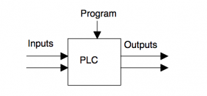
Figure 1. Basic Process of a PLC
Advantages
PLCs are advantageous because it helps eliminate the process of rewiring to change certain functionalities of a control system since the operator can simply make appropriate changes to the program that the PLC is using to control the system. This advantage contributes to the flexibility and cost effectiveness of using PLCs for controlling machines. PLCs were designed to be used for carrying out control tasks and surviving harsh industrial environments that it may be exposed to. PLCs are able to bear exposure to vibrations, temperature, humidity, and noise. PLCs are relatively easy to program and usually use easily understood programming language since it was not designed so that only computer programmers are able to use it. PLCs can range from small units with about 20 digital inputs/outputs to modular systems with large numbers of digital inputs/outputs. PLCs can be used for either digital or analogue inputs/outputs, and it can also be used with PID control modes.
PLC System
Figure 2 shows the main parts that make a PLC system.
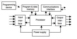 Figure 2. Components of a PLC System
Components
Control Process Unit (CPU) – Contains the Microprocessor. Responsible for interpreting the input signals and carrying out the tasks that is stored in its memory, then communicates the action signals to the outputs
Power Supply Unit – Used for conversion of a.c. voltage to low d.c. voltage (5V) that is needed for processor and circuits in input and output interface modules
Programming Device – Used to write out the program for desired tasks. Program is then transferred to memory unit of PLC
Memory Unit – Unit where program for control actions is stored. This is also where the data is stored for inputs and outputs
Input and Output Section – Sections where processor receives a signal from external devices that the communicates it to another external device. Input and Output devices give signals that can be classified as discrete (on or off), digital (on or off), and analogue (signals whose size is proportional to the size of the variable being monitored).
Communication Interface – Used to receive and transmit data on communication networks from or to other remote PLCs. It relates to device verification, data acquisition, synchronization between user applications and connection management.
Ladder Logic Programmming
Ladder programming is a way of programming PLCs. The method of ladder programming can be compared to drawing a switching circuit. Ladder diagrams look like a ladder where the vertical lines are the power rails and the horizontal lines are where the circuits are connected.
Basic Conventions of Ladder Programming
-The vertical lines (rungs of the ladder) show the power rails where circuits are connected. Power flows from the left side of the power rail and across the rung.
-Each vertical line represents an operation in the control process
-A ladder diagram is read from left to right for each rung and from top to bottom
-Each rung of the ladder diagram has to begin with at least one input and has to end with an output.
-Electrical devices are represented as the normal conditions for the device. For example, a switch for a device that is normally open until something closes it will be shown as open in the diagram
-A device can be assigned to more than one rung of a ladder. For example, a relay that is used to switch more than one device can be used and the relay will have an assigned label that will be used throughout the diagram.
-Inputs and Outputs can be identified by their assigned addresses, which is dependent on the notation used by the PLC manufacturer. The addresses of the inputs and outputs are what will be stored in the memory of the PLC.
Applications/Examples
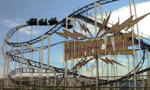
Roller Coasters
A PLC can be used for controlling operations of roller coasters. The PLC system can control the air compressor and braking systems. It can determine the right positioning of the train cars and can help determine when the train rides are allowed to go to the next position in the roller coaster ride without danger or damage. The PLC system can be programmed to monitor proper functioning of brake systems. When a problem in the brake system is determined, the PLC will sound an alarm and automatically shut down the ride.
 https://www.automationworld.com/article/technologies/plcs-pacs/roller-coaster-overhaul
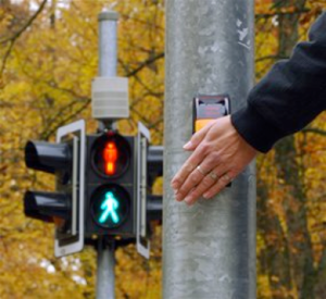
Light traffic control
At crosswalks, there are buttons for people to push in order to get the signal for walking. When a person pushes the button, the push of the button triggers an input that gets analyze by an input device scan. Once the device processes it, it follows an output with a walking signal.
http://www.abc.net.au/science/articles/2010/05/04/2889699.htm
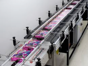
Food Industry
Food manufacturers use PLCs to automate conveyor lines to be able to produce a certain amount of a product in a limited amount of time while providing high quality products. Automated conveyor lines can increase efficiency because it allows the manufacturers to produce certain products at faster rates, and minimal steps.
https://www.foodonline.com/doc/smart-conveyors-maximize-efficiency-on-food-packaging-lines-0001
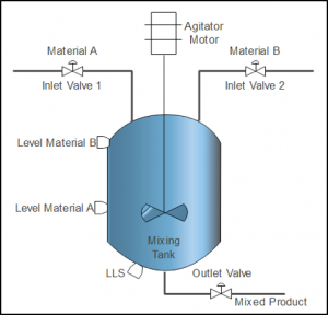
Batch Mixing in a Tank
A PLC can be used for mixing two different materials in a tank. Level switches are used to detect the levels of the two materials. A level switch is used at the bottom of the tank to determine if level is low. Once the levels are determined, there are valves that will open to let the materials into the tank. An agitator connected to a motor shaft is used to mix the two materials together once the materials are in the tank. The system is set to a particular time for the materials to be mixed together. Once the timer is up, an outlet valve is used to drain out the mixed materials.
https://www.sanfoundry.com/plc-program-control-mixing-


