
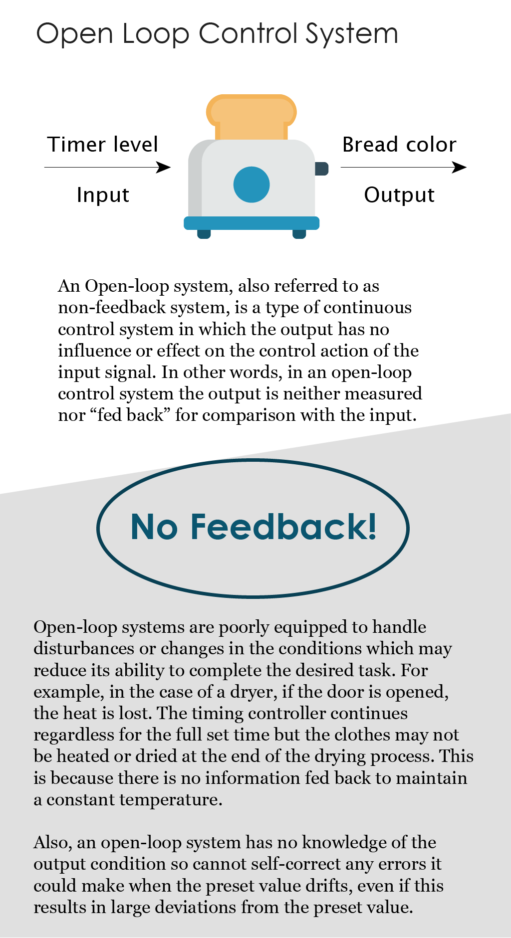
A stepper motor or step motor or stepping motor is a brushless DC electric motor, which means it rotates continuously when a DC voltage is applied to their terminals. They are typically used in open-loop control systems. Before learning more about stepper motors, it is important to understand open-loop control. Here’s a brief introduction.
Stepper motors continued
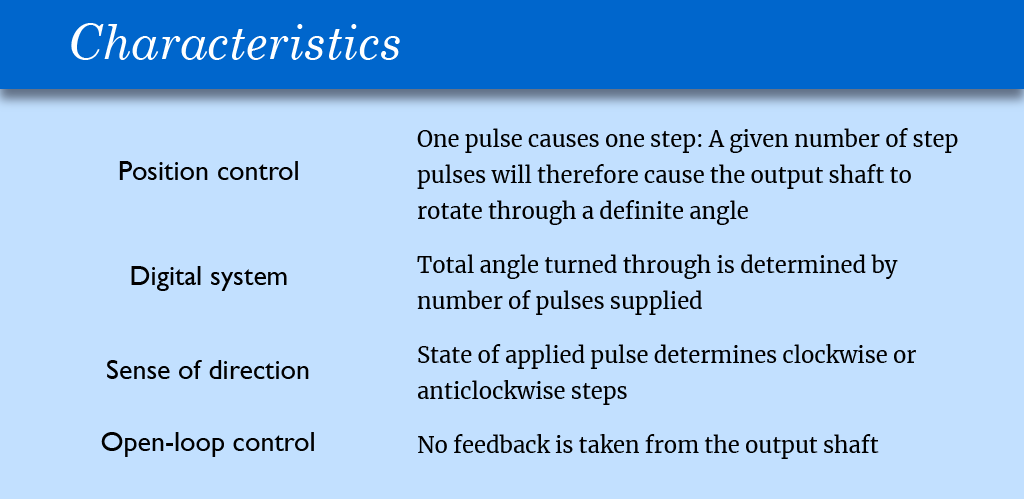
The unique feature of stepper motors is step control. The output shaft rotates in a series of discrete angular intervals, or steps, one step being taken each time a command pulse is received. When a definite number of pulses has been supplied, the shaft will have turned through a known angle, and this makes the motor well suited for open-loop position control.
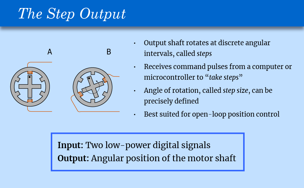
A stepper motor with a soft iron rotor, with active windings shown. In ‘A’ the active windings tend to hold the rotor in position. In ‘B’ a different set of windings are carrying a current, which generates torque and rotation.
Image source: https://commons.wikimedia.org/wiki/File:Stepper_motor.svg
Step Speed
Each step is completed very quickly, usually less than a millisecond; and when a large number of steps is called for the step command pulses can be delivered rapidly, sometimes as fast as several thousand steps per second. At these high stepping rates the shaft rotation becomes smooth, and the behavior resembles that of an ordinary motor.
As a general guide we can assume that the torque and power of a stepping motor will be similar to the torque and power of a conventional totally enclosed motor of the same dimensions and speed range. Step angles are mostly in the range 1.8° – 90°, with torques ranging from 1 μNm up to perhaps 40 Nm in a motor of 15 cm diameter suitable for a machine tool application where speeds of 500 rev/min might be called for, but the majority of applications use motors which can be held comfortably in the hand.
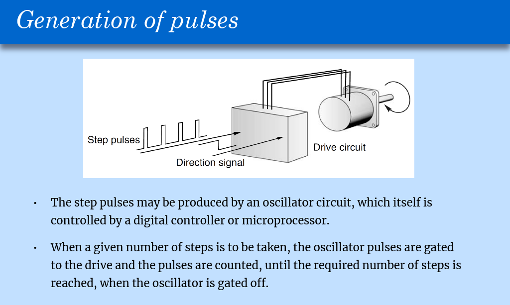 The following figure illustrates a six-step sequence. There are six step command pulses, equally spaced in time, and the motor takes one step following each pulse.
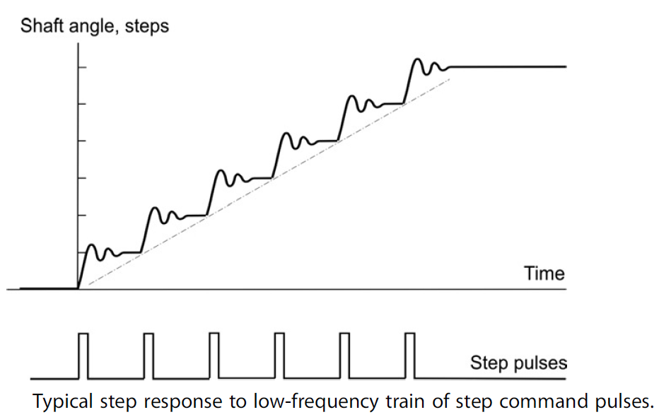
Three important general features can be identified with reference to the above figure.
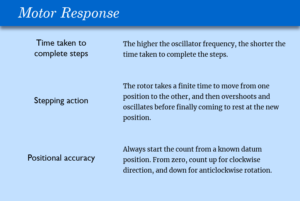
First, although the total angle turned through (six steps) is governed only by the number of pulses, the average speed of the shaft (which is shown by the slope of the broken line in the figure) depends on the frequency. The higher the frequency, the shorter the time taken to complete the six steps.
Secondly, the stepping action is not perfect. The rotor takes a finite time to move from one position to the next, and then overshoots and oscillates before finally coming to rest at the new position. Overall single-step times vary with motor size, step angle and the nature of the load, but are commonly within the range 5–100 ms. This is often fast enough not to be seen by the unwary newcomer, though individual steps can usually be heard; small motors ‘tick’ when they step, and larger ones make a satisfying ‘click’ or ‘clunk’.
Thirdly, in order to be sure of the absolute position at the end of a stepping sequence, we must know the absolute position at the beginning. This is because a stepping motor is an incremental device. As long as it is not abused, it will always take one step when a drive pulse is supplied, but in order to keep track of absolute position simply by counting the number of drive pulses (and this is after all the main virtue of the system) we must always start the count from a known datum position. Normally the step counter will be ‘zeroed’ with the motor shaft at the datum position, and will then count up for clockwise direction and down for anticlockwise rotation.


