
6 Step Procedure:
Follow this 6 Step Procedure to select the best Ball Screw Assembly for your needs. Visit Bosch Rexroth’s LMT Handbook for any further details you need.
For a quick tutorial on how to use the online configurator from Bosch Rexroth follow this link: https://www.youtube.com/watch?v=yBmVW5dJLCA&t=5s
1. Defining the requirements (LMT Handbook Section 5.1.3.1)
-
- Ball screw drive
- Application layout
- Dynamic cycle
- Load scenario
-
- Ball Screw Drive The following details need to be known to perform design calculations.
- Ball Nut Type
- Size
- Nut Dimension
- Characteristics

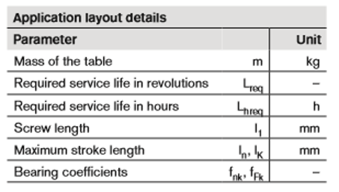
- Application Layout Details on what the ball screw will be used for, what masses will the ball screw move and what type of end bearings will it use. This information determines the ball screws service life.
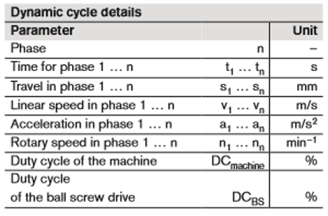
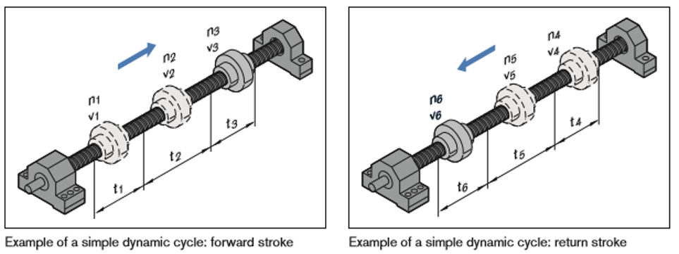
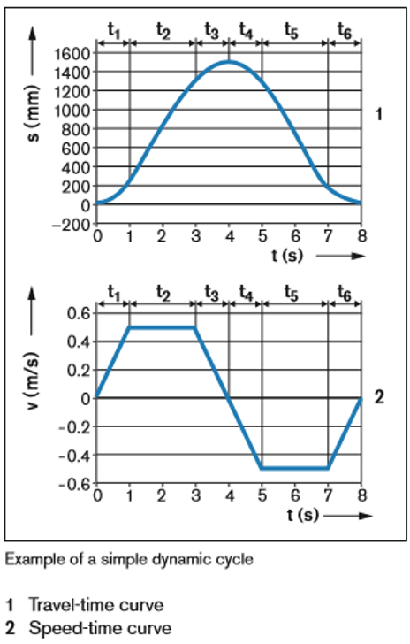
- Dynamic Cycle The dynamic cycle shows the different motions that the ball screw will go through. Motions like acceleration, breaking, processing, etc. For each of these motions, the time, travel, linear speed, acceleration and rotary speed has to be determined.
- Load Scenario A Ball Screw can only work with forces in the axial direction. This can include weight forces Fg, acceleration Forces Fa, process Forces Fp, and friction Forces FR .
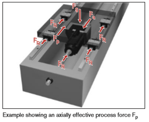
The Forces are calculated using the following equations: Fg=m*g m = mass Fa=m*a g = gravity = 9.81m/s^2 a = accelerationThe friction Force is opposite to the direction of movement.
- Ball Screw Drive The following details need to be known to perform design calculations.
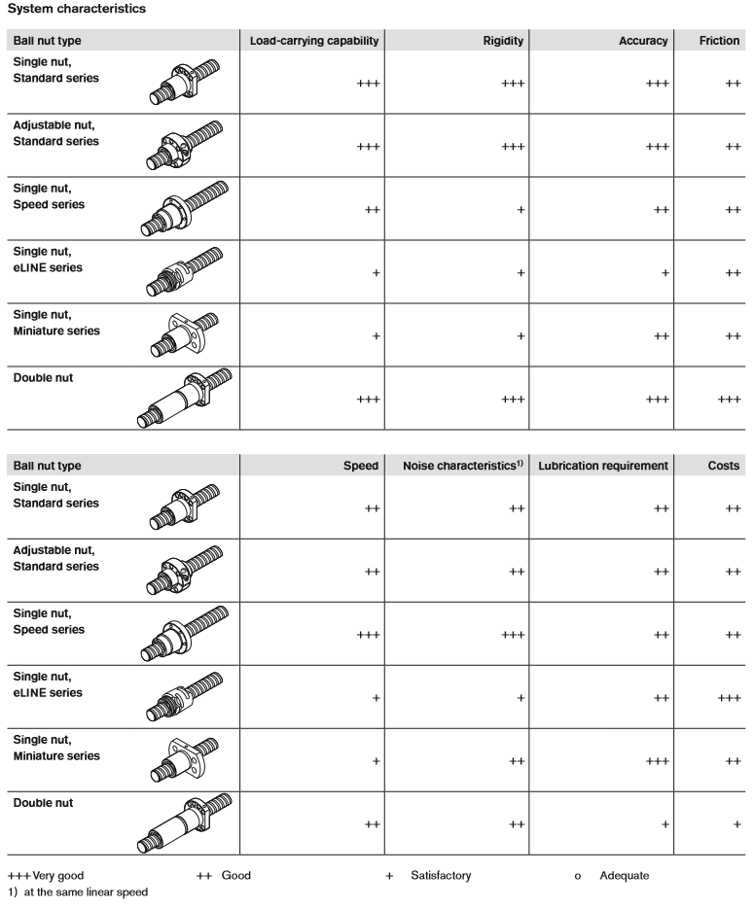
2. Select the appropriate ball screw assembly (LMT Handbook 5.1.2.1 & 5.1.2.3)
Use the Selection Guide below to determine which system fits your needs best.
3. Calculate the Life Expectancy (LMT Handbook Section 5.1.3.2)
-
- Nominal Life: the amount of revolutions or hours the Ball Screw can operate at a constant speed, before any initial signs of failure become evident. Nominal Life in Revolutions:
Nominal Life in Hours:
- Average Rotary Speed:
nm = average rotary speed (min-1) n1…..nm = rotary speed in phase 1….n (min-1) qt1…..qtn = discrete time steps in phase 1….n (%)
- Equivalent Dynamic Axial Load:
- For the Ball Screw experience constant speed use:
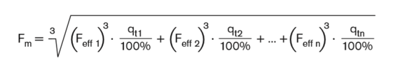
- For the Ball Screw experiencing varying speed use:
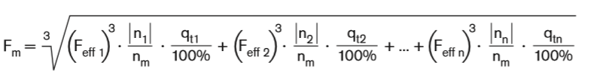 Fm= equivalent dynamic axial load (N) Feff1…Feffn= effective load during phase 1…n (N)
- For the Ball Screw experience constant speed use:
- Nominal Life: the amount of revolutions or hours the Ball Screw can operate at a constant speed, before any initial signs of failure become evident. Nominal Life in Revolutions:
4. Calculate the Critical Speed (LMT Handbook Section 5.1.3.3)
Critical speed is the lowest rotational speed at which the Ball Screw is equivalent to its first order frequency, resonance. The critical speed depends on the end bearings, the diameter of the screw’s core, and the critical screw length.
= coefficient as a function of end bearings
= screw core diameter (mm)
= bearing to bearing distance (mm)
= critical screw length for preloaded nut systems (mm) (For nuts with backlash:
)
Note: The speed of the Ball Screw should never be operating at a higher rate than 80% of the critical speed. Therefore calculate the permissible speed.
= critical speed (min-1)
= permissible operating speed (min-1)
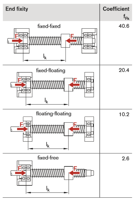
To help find , decide what type of end fixity you need, use Table below:

5. Calculate the permissible axial screw load (LMT Handbook Section 5.1.3.4)
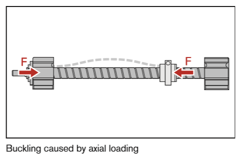
Axial Screw Loads are created by acceleration, friction, weight and process forces on a Ball Screw. A factor to take into account is buckling stress, this occurs when the screw shaft is exposed to a compressive force in the axial direction, which creates a bend in the screw shaft. An example of buckling can be seen below.
Use the following formula to calculate the theoretical buckling load of the screw:
Find the permissible axial load on the screw. This is the value you will use to choose a ball screw drive because it includes safety factor calculations.
= theoretical buckling load of the screw (N)
= permissible axial load on the screw in service (N)
= coefficient as a function of the end bearings
= screw core diameter (mm)
= effective buckling length of the screw (mm)
To find the coefficient of the end bearings, choose what your needs are for the end bearings from the graph below:
6. Calculate the drive torque and the drive power (LMT Handbook Section 5.1.3.6)
- Drive Torque : is what causes the screw to rotate. It is the conversion of rotary motion to linear motion.
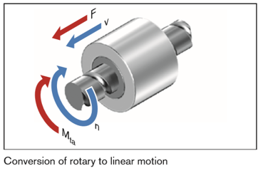
- The transmitted torque: is when the thrust force F is in the axial direction to move the screw. It is the conversion of linear motion to rotary motion.

F = operating load (N) P = lead (mm)
= mechanical efficiency – for drive torque =0.9 – for transmitted torque =0.8
- To calculate an initial estimation of the Drive Power:
Pa = drive power (kW) n = rotary speed (min^-1)


