
Looking for an interactive design process to help purchase items for your next project? Click here to see the advanced Bosch Rexroth GoSelect™ tool that makes designing a breeze! GoSelect is a streamlined tool that essentially designs your project for you. Go select will walk you through what parts you would like to add to your product and what sizes you will need. At the end, a bill of materials will automatically be generated and can be added to your shopping cart. Below are step by step instructions on how to use the GoSelect system, as well as the Profile Rail systems PDF Guide method (more calculation and theory based).
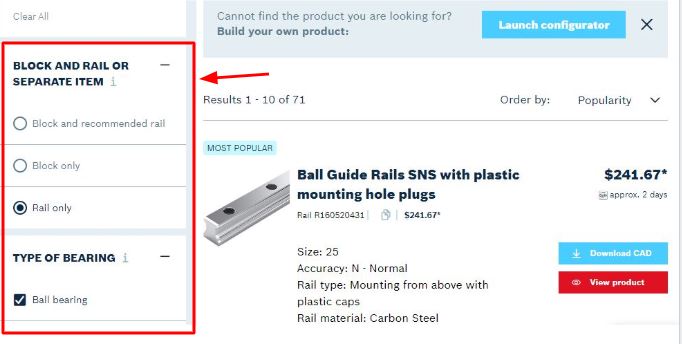
- Use the “Launch Configuration” button to use the interactive designer, or use the left side to refine the products shown based on your project needs.
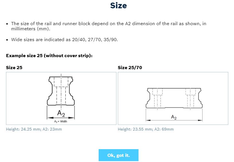
- Begin designing! The system will ask what size and mechanical format of Roller Rails you would like to use. If you are unsure what size or format to use, visit our page on sizing, characteristics, and designs.
- Follow the design steps until your custom product inscription displays. This page will appear as below:
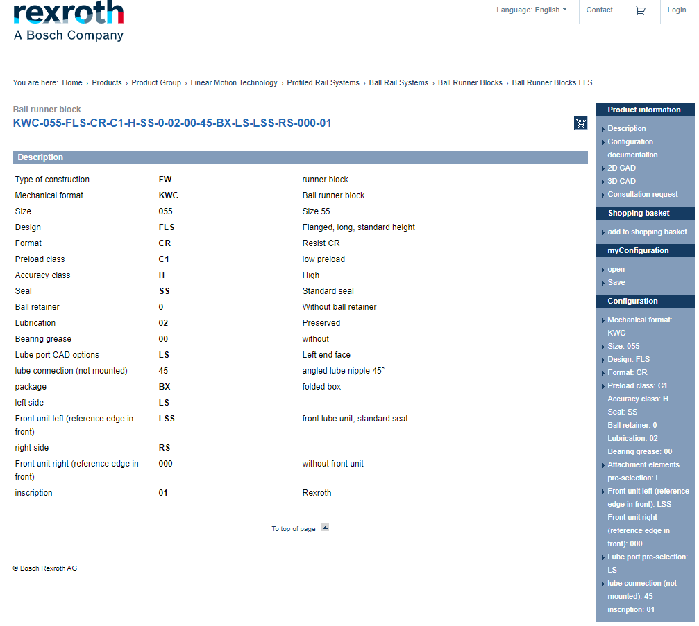
- Your item can be added to your shopping cart by clicking the blue shopping cart icon located next to the product information column.
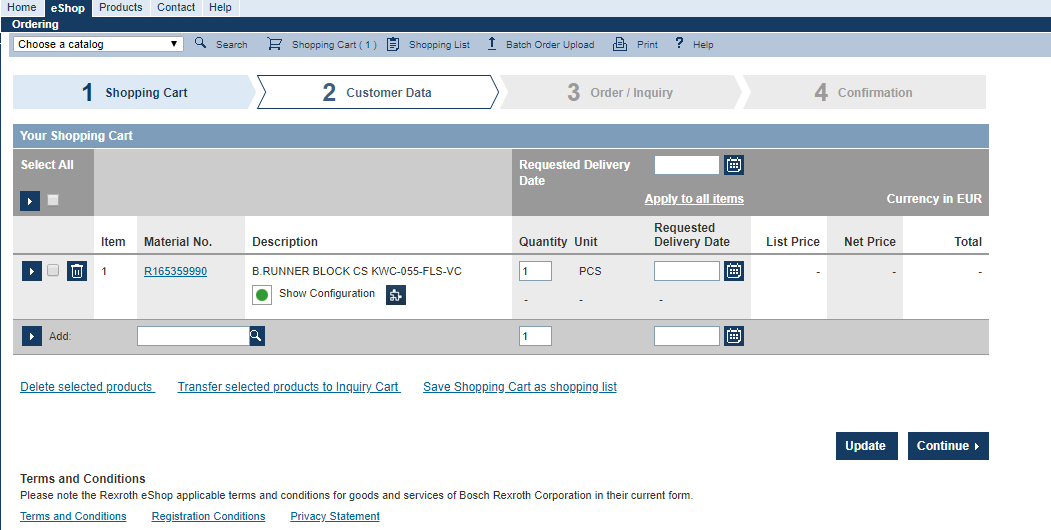
- Your product is now ready to be ordered and shipped!
If you are unsure about the different accessories and sizes for products, you can always follow the “Linear Profiled Rail Systems Selector” link below and use the info icons. This step by step tutorial will show an alternate way to find parts.
- Click this link to go to the Linear Profiled Rail Systems Selector page
- Use the left side bar to navigate through the different selection criteria. Your screen should look like this:
- The “i” icon will lead you to a very brief and straight forward explanation on what you’re selecting
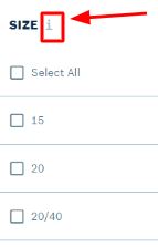
- An image will appear on your screen showing the following:
Follow these steps until you have completed your design! Happy hunting!
Here is the “Textbook” method to finding the right parts for your next project. This process is a lot more tedious and methodical, but ensures the right parts.
Many different parameters must be considered to arrive at the optimal choice of profiled rail guide. Though the selection procedure described below is a typical one, it may not apply to all applications. For some applications it may be useful to switch the order of the steps involved. Often, the starting situations will be different. While new-build projects generally give designers full freedom of choice, the range of available options
will be restricted at the outset when modifying existing designs. Also, some types of guide are more commonly used in certain sectors and applications than in others. Another point to be considered at an early stage is the level of accuracy required, as this may eliminate some versions in the first place. It is therefore advisable to run through all the steps once to gain a better idea of the possible options before proceeding to select the product and perform the nominal life calculations.
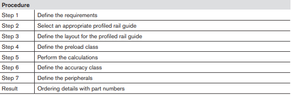
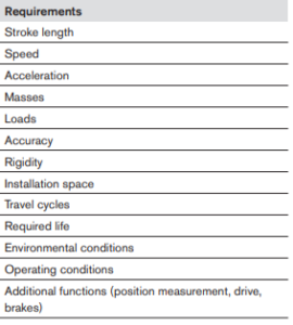
Step 1: Define the Requirements
When selecting profiled rail systems, the first step is to define the requirements and operating conditions for the application, as shown below.
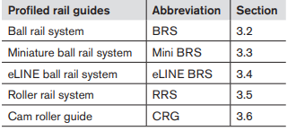
Step 2: Select an Appropriate Profiled Rail Guide
The next step is to roughly calculate or estimate the expected loads for the individual runner blocks. The appropriate profiled rail system (type, size and runner block design) can then be selected using the load capacities and the selection charts. The load capacities can be found in the respective Rexroth product catalogs. The static and dynamic load ratios (C0/F0max and C/Fmax) must also be taken into account here. The selection tables were introduced in Section 3.1.2.1. They refer to the sizes, runner block designs, and system characteristics.
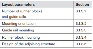
Step 3: Define the Layout for the Profiled Rail Guide
The layout for the profiled rail system now has to be defined (see section 3.1.3). Define the number of runner blocks and guide rails first. Then define the mounting orientation (horizontal, vertical, inclined, wall mounting or overhead mounting). Finally, determine how the guide rails and runner blocks are to be mounted and fastened, keeping the location and use of the reference edges in mind.
Step 4: Define the preload class
The preload class is chosen on the basis of the required rigidity. The rigidity charts should be consulted to check whether the desired rigidity will be achieved. If this check shows that the rigidity will not be high enough, the linear guide must be redimensioned. The tables listing the preload classes according to areas of use and applications can be used as a rough guide here.
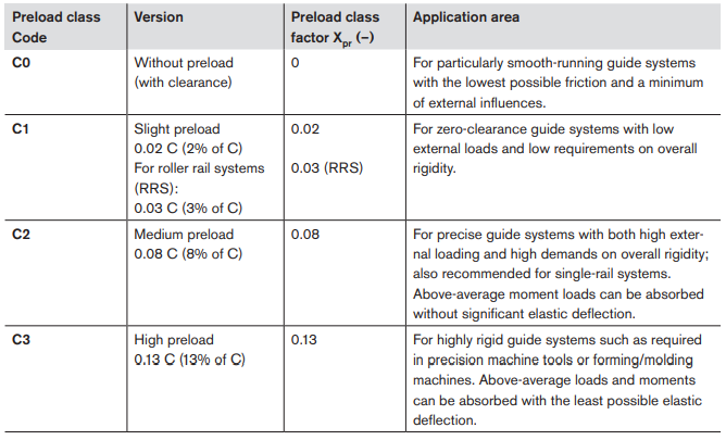
The preload force for a particular preload class can be calculated using the respective preload class factor Xpr. This internal loading of the runner block must be taken into account when calculating the life expectancy.
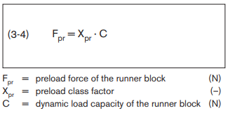
Example for a size 25 runner block with a load capacity C of 22,800 N and preload class C2:
Fpr = Xpr · C = 0.08 · 22800 N = 1824 N
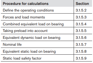
Step 5: Calculations
Using the available data, calculate the nominal life and the static load safety factor. If the required values are not met, repeat steps one to four and select a more appropriate profiled rail guide. Rexroth provides a special design calculation service to assist with nominal life calculations
Step 6: Define the Accuracy Classes
Once the nominal life requirements are fulfilled, the next step is to define the accuracy class. This depends heavily on the area and application in which the linear guide is to be used. Help is provided in the form of selection charts and tables. See section 3.1.1.5.
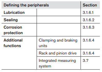
Step 7: Define the Peripherals
The last step is to define the peripherals for the linear guide. This includes specifying the lubrication system and the in-service lubrication intervals. Adequate protection against life-shortening factors must be also be selected, i.e. appropriate sealing and corrosion protection. Rexroth linear guides can be equipped with additional functionalities such as clamping and braking units, rack and pinion drives, and integrated measuring systems.
Result: Ordering details with part numbers
After this final step, all the required ordering details are known, including the part numbers for the runner blocks, guide rails and the required accessories. Lastly it may be important for cosmetic or personal preferences to include accessories. See the below section to view the accessories that will make your profile rail system above the rest!
Back to Profile Rail Systems Main Page


