
The following types of calculations are critical for the analysis of linear motion systems:
- Life Expectancy
- Motor Sizing
- Deflection
Life Expectancy
The life expectancy of linear motion systems are usually calculated in a similar vein as profiled rail systems, with the calculations performed as if the carriage were a single runner block. In general, loads up to 20% of the characteristic dynamic capacities are considered acceptable.
It is important to note the orientation of the linear motion system for calculations, as that determines the orientation of the loads with respect to the runner block direction of travel.
If the linear motion system comes with a ball screw assembly, the life expectancy of the ball screw assembly and (if applicable) the fixed bearing must be taken into account when determining the life expectancy of the linear motion system.
Motor Sizing
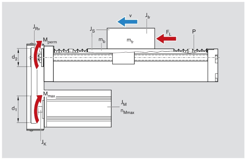
Motion systems with ball screw or toothed-belt drive units require a motor in order to properly drive the system. Therefore, it is important to properly size the motor in accordance with the application of the linear motion system. The following formulas detail the calculations for motion systems with ball screw assemblies but can also be used for sizing motors for linear motion systems with toothed belt drives.
Important Parameters for Motor Sizing
- The Mounting Orientation of the Motor
- The frictional torque of the system, denoted as
- The frictional torque of the given side drive, denoted as
- The gear ratio of the motor and the side belt drive (if using a side belt drive, denoted by
)
- The screw lead, denoted by
- The force of thrust, denoted as
- The mass of the carriage and load
- The total mass of the system
Frictional Torque
The frictional torque of a motor is the amount of torque that is required by the motor in order to resist frictional forces. The following equations give the frictional forces for motors with a mount and coupling attachment:
And the following equation gives the equation for frictional torque for a motor with a timing belt side drive:
Where for both equations:
is the frictional torque at the motor journal
is the frictional torque of the system
is the frictional torque of the timing belt
The values of and
for Bosch products can be found in the Bosch catalogs.
Load Torque
The load torque is the amount of torque a motor experiences in response to a load, the following formula calculates the moment
Where:
is the load torque
is the load
is the screw lead
is the gear ratio
Weight Torque
The weight torque is the amount of torque the moment has to produce in order to counteract the weight of the system. The weight torque is only applicable to systems if the weight of the load is parallel to the movement (aka if the mounting orientation is vertical). Therefore, if the mounting orientation is horizontal the weight torque is zero.
If the mounting orientation is vertical, the equation for the weight torque can still depend on whether the base plate or the carriage is fixed. If the base plate is fixed while the carriage travels, then the weight moment is:
If the carriage is fixed while the base plate moves, then the weight moment is:
For both equations:
is the weight torque
is the transmission ratio
is the screw lead
is the carriage’s mass
is the mass of the external load
is the total mass of the system
Acceleration Torque
The acceleration torque of the motor is the amount of torque the motor has to have in order to accelerate the load. The maximum acceleration torque of the motor is given by the following:
Where
is the maximum acceleration torque in Newton meters
is the maximum torque of the motor in Newton meters
is the frictional torque in Newton meters
is the weight torque in Newton meters
is the load torque in Newton meters*
*If the load torque acts in the direction of the movement, is positive. Else, if acting opposite the direction of motion,
is negative.
Mass Moment of Inertia
The mass moment of inertia of a motor system with an external load can be calculated as the following for motors with a mount and coupling:
The mass moment of inertia of a motor system with an external load can be calculated as the following for motors with timing belt side drive
Where:
is the mass moment of inertia of the external load
is the mass moment of inertia of the system with external load
is the mass moment of inertia of the coupling
is the mass moment of inertia of the brakes
is the mass moment of inertia of the timing belt drive
The total moment of inertia on the journal channel can be calculated by:
Transmission Ratio
Denoted by the letter i, the transmission ratio is the ratio between the driving sprocket speed and the driven sprocket speed. The transmission ratio can be calculated by the following:
Where:
is the transmission ratio
is the diameter of the sprocket on the motor shaft in mm
is the diameter of the sprocket on the screw shaft in mm
is the rotational speed of the motor in rotations per minute, or RPM
is the rotational speed of the screw in RPM
Motor Speed
The speed of a motor is determined by the shaft speed and the transmission ratio, the motor speed is related the shaft speed by the following relationship:
The shaft rotational speed for the screw is dependent on the linear speed of the shaft and the pitch of the screw. In one rotation of the screw, the carriage will have moved a distance equal to the pitch of the screw. Therefore the shaft rotational speed is equal to:
Where:
is the maximum linear speed of the motor in m/min
is the pitch of the screw in meters
However, most of the time, the pitch of the screw is measured in millimeters, therefore the speed of the shaft will be calculated by:
Where is the pitch of the screw in mm
Therefore the formula for the maximum motor speed given the maximum linear speed and the pitch of the screw is the following:
Acceleration of the Motor
The acceleration of the motor can be calculated by the following formula:
Where:
is the linear acceleration of the motor
is the maximum linear speed of the motor
is the acceleration time, or the amount of time it would take to accelerate from rest to top speed.
Acceleration Time
The acceleration time of a motor, tb can be calculated by the following
Where:
is the total moment of inertia
is the rotational speed of the motor
is the acceleration torque of the motor
Acceleration Travel
With the acceleration time, one can find the acceleration travel, or the amount of distance one expects the system to travel while accelerating from rest to top speed.
Deflection
The linear module has the option to be unsupported except for at the ends. If left in the unsupported configuration, the deflection can cause the linear motion system to lose some of its accuracy. Therefore, it is important to calculate the deflection of a linear motion system when left in an unsupported state.
Most Bosch manuals provide the user with graphs that plot the deflection of the module against the length of the motion system against many different forces. The plot also gives the maximum deflection the motion system should be at given the length of the module. The plots can be used to determine the maximum load of the module given its load, as well as the safety factor of the module in regards to deflection.
The chart below gives an example plot for a MKK 20-80 linear motion system:
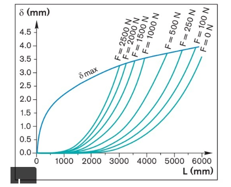
Sample Deflection Chart for a MKK 20-80.


