
Introduction
Pneumatics is a method of providing motion by using compressed air. Pneumatic systems use compressors to store a volume of air. Control valves and piping are then used for direction and flow rate of the stored air to provide air to the actuator of the system. The actuators are then used to provide movement to the system by transforming the stored energy in the compressed air into kinetic energy. When designing a pneumatic system, the following four factors must be considered:
1. Type of air compressor to use
There are many different types of air compressors that exist in the industry today. Air compressors can be divided into two categories. One category is a Positive Displacement compression. Positive displacement compressors work by taking in a volume of air in a chamber. The volume of the chamber is then reduced to compress the air that was drawn in. Positive displacement compressors include reciprocating piston compressors, rotary screw compressors, rotary vane compressors, and scroll compressors. The second type of air compressor is called a dynamic displacement type of compressor. Dynamic displacement compressors use rotating impellers to bring the air to a high velocity. The flow of the air is then restricted and released through diffuser that results in the decrease of velocity, which then causes an increase in pressure. Axial compressors and centrifugal compressors are types of dynamic displacement compressors.
2. Air Distribution in the System
When deciding on the piping to distribute air flow, several factors have to be considered. Factors such as sharp angles, moisture, blockage can have big effects on the efficiency of a pneumatic system. Piping material also needs to be considered. Plastic or metal are the two basic options for pneumatic designs. Each type of material offer has its own advantages and disadvantages that have to be considered depending on the purpose and design of the system.
3. Controlling the Air in Pneumatic System
Choosing the right valves to regulate system pressure, flow rate, and direction of flow are imperative to a proper pneumatic design system. Determining the right type and size for the system are important because control valves that are too big will end up being a waste of money because air will be wasted and control valves that are too small may lead to the actuator to not work correctly.
4. Actuators to be Used to Move System
Actuators in a pneumatic system are used for providing linear or rotary motion from compressed air. There are many different types of actuators such as diaphragm cylinders, rodless cylinders, telescoping cylinders, and through rod cylinders. The most common style of an actuator is composed of a piston with moving rod contained in the cylinder. This style can be divided into two categories. Single-acting cylinders are best used when providing unidirectional motion. They work by drawing in compressed air into the cylinder through a single port, so that the piston can be moved to certain position. The other type of cylinder is a double-acting cylinder. Double-acting cylinders are able to provide two-way motions because of the two ports located at each end of the cylinder. The two ports at each end allow the piston to be moved back and forth by alternating which end draws in the compressed air.
Pneumatic systems offer a number of advantages and applications. One of the most obvious advantage is that it uses air, which is readily available anywhere. Air can be stored in tanks and depending on the size, the storage capability allows for easier transportation. Pneumatic systems are composed of simple components that are fairly easy to design together to be able to provide motion.
Basic Theory
Definitions:
A Compressor is a mechanical device that covert mechanical energy into fluid energy.The compressor increases the air pressure by reducing its volume which also increases the temperature of the compressed air. The compressor is selected based on the pressure (psia) it needs to operate and the delivery volume(cfm).
There are two types of compressors:
Type 1. Positive displacement compressors that work by mechanically changing the volume of the working fluid, this type can be a reciprocating or rotating system.
Type 2.Dynamic compressor that works by mechanically changing the velocity of the working fluid, this can be centrifugal, axial or ejection.
Receiver is sometimes called a pressurized tank, it can reduce the flow pulsation of the piston air compressor, improve the continuity and pressure stability of the output air, further precipitate and separate the water and oil in the compressed air, and ensure the continuous supply of sufficient gas.
Two types of receiver:
Type 1.Paint containers are used in most cases, in which case the air receiver is not affected by extreme weather conditions and the completely clean air is not an absolute prerequisite. Paintwork ensures corrosion protection.
Type 2. The galvanized container is treated with glass enamel to make it waterproof and steam resistant. The complete reliability of this type of treatment is the result of the association of inorganic components between metal surfaces. After being baked at 850-degree temperature, it no longer absorbs water and fully protects the vessel from corrosion.
https://www.lindiridis.gr/wp-content/uploads/2010/09/AIR-RECEIVERS.pdf
Formula Size


A control valve is used in directing or blocking the fluid flow, it regulates the flow of the fluid in the pneumatic system. A control valve may be connected to a computer system that tells it when to open and when to close in order to move the actuator. Depending on the application, you can use a needle control valve, a ball control valve, or a butterfly control valve.
Actuator: a piston that provides mechanical energy transmission
Air cylinders and motors are used to obtain the required movements of the mechanical elements of the pneumatic system.
The actuator is the output devices that convert energy from pressurized hydraulic gas or compressed air into the required type of action or motion. In general, hydraulic or pneumatic systems are used for gripping and moving operations in the industry. These operations are carried out by using actuators.
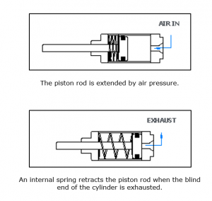
Single acting cylinder
image source https://nptel.ac.in/courses/112103174/pdf/mod6.pdf
The compressed air pushes piston located in the cylindrical barrel causing the desired motion. The return stroke takes place by the action of a spring. Generally, the spring is provided on the rod side of the cylinder
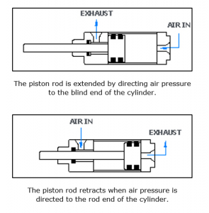
Double acting cylinder
image source https://nptel.ac.in/courses/112103174/pdf/mod6.pdf
The double-acting cylinder is a cylinder in which the working fluid alternates on both sides of the piston. In order to connect the piston in the double-acting cylinder to the external mechanism, double-acting cylinders are common in steam engines but are typically double-acting cylinders that use them to generate forces in both directions. The double-acting hydraulic cylinder has a port at each end that provides hydraulic oil for the contraction and expansion of the piston. When a double-acting cylinder is used, the external force cannot be used to retract the piston, and it can also be used in situations where both directions require a large force.
Cylinder end cushions
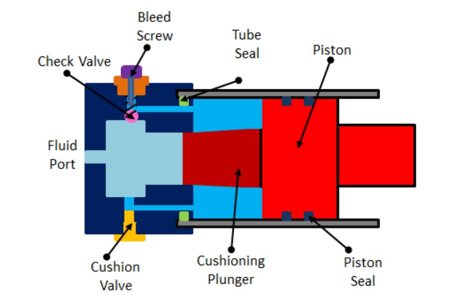
image source https://nptel.ac.in/courses/112103174/pdf/mod6.pdf
Double acting cylinders typically include a cylinder head at the end of the cylinder to slow the movement of the piston near the end of the stroke. The cushioning device avoids damage due to impact when the rapidly moving piston is blocked by the end cap. Deceleration of the piston begins when the tapered plunger enters the opening in the lid and closes the main fluid outlet. This limits the exhaust. Flowing from the barrel to the port. This throttling results in a decrease in the initial speed. During the last part of the journey, the oil must pass through an adjustable exhaust the autonomous fluid outlet opens and closes. Therefore, the remaining fluid is present through the buffer valve. The amount of buffer can be adjusted by a buffer screw. Provide a check valve to achieve rapid separation away from the end position during this period retracting movement. Check valve with built-in vent screw to vent air. Air bubbles are present in the hydraulic system.
Gear motor: a rotary actuator

image source https://nptel.ac.in/courses/112103174/pdf/mod6.pdf
It consists of two intermeshing gears inside a housing, one of gear connected to the drive shaft of the housing. Air ingress starting from the inlet, the rotational pressure of the meshing gear is generated due to the difference and torque is generated. Air is present from the exhaust vent. Gear motor tends to leak at low speeds and is therefore often used in medium speed applications.
Vane Motor: a rotary actuator
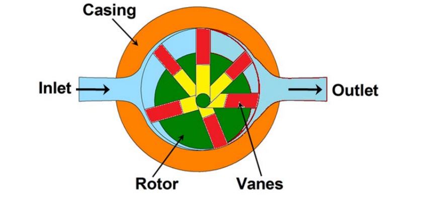
image source https://nptel.ac.in/courses/112103174/pdf/mod6.pdf
The rotary vane motor includes a rotor on which a sliding vane rotor is disposed. The rotor and housing are placed eccentrically. Air enters from the inlet, causing the rotor to rotate, producing torque. The air is then discharged from the exhaust port (outlet).
Limited rotation actuators
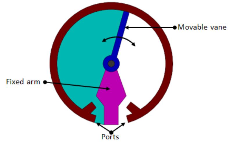
image source https://nptel.ac.in/courses/112103174/pdf/mod6.pdf
It consists of a single rotating blade connected to the output shaft. It is used for dual action operation with a maximum angle of rotation of approximately 270°. These are commonly used in the application of actuated dampers in robotics and material handling. Other types of limited rotary actuators are rack and pinion actuators.
Working principle of air compressors: Boyle’s Law
Statement: For a given mass, at constant temperature, the pressure times volume is a constant
PV = C
For example, in the figure shown, we have a volume of gas V1 at pressure P1. This gas is compressed to volume V2, which will result in a rise of pressure to P2, where
P1V1 = P2V2
provided the temperature of the gas does not change during compression.
This formula is only valid when absolute units are used: Pressure in Pascals and Volume in m3
In practice, compression of a gas is always accompanied by a rise in temperature (as is commonly noticed when pumping up a bicycle tire) and a reduction in pressure produces a temperature fall (the principle of refrigeration). For the above equation to apply, the gas must be allowed to return to its original temperature.
Governing equations
Pressure, Force and Area
Pressure occurs in a fluid when it is subjected to force. In figure shown, a force F is applied to an enclosed fluid via a piston area A. This results in a pressure P in the fluid. Increasing the force increases the pressure in direct proportion. Decreasing piston area also increases pressure. Pressure in the fluid can therefore be defined as the force acting per unit area, or:
Use the above equation to find out the pressure necessary to extrude the required force from the pneumatic actuator. For example, let’s calculate the pressure required to generate a force of 10 N from a piston of diameter 2cm.
When retracting, no force can be applied where the connecting rod is attached to the piston, therefore the working area is reduced. The formula changes to:
To find out pneumatic cylinder velocity (actuator piston velocity) use the following equation:
Where S is velocity in m/s, Q is air flow in m3/sec and A is area in m2
Applications/Examples
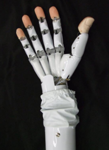
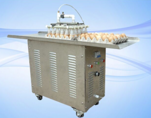
Pneumatics is also used when a special, delicate touch must be made to the products. For example in egg factory they use suction cups to transfer eggs without breaking them.
 Typical Operating Characteristics of compressors(US Units)
source: Process Industry Practice Machinery,PIP REEC001,Compressor selection guideline.
The selection of a compressor also depend on :
- Limiting fluid proprieties (dew point,temperature,specific volume,…)
- Duty cycle
- Maximum flow rate
- Location, site elevation,voltage and phase required
- Maximum suction pressure and temperature
- Selected accessories
Steps to Approaching Final Design
Here’s a video on how to choose parts for a pneumatic system:
Make sure that pneumatic is the correct way to go to approach your design.
- Choose what type of pneumatic cylinder wanted to be used in your design. There are several types of pneumatic cylinders with different purposes.
- Single Acting: Provides power only on extension of the stroke “push”. a Required separate force which is usually an internal spring is required to return the piston to its original position.
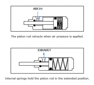
- Reverse Acting: is similar to single acting, but the port is on the opposite end to provide power on retraction stroke “pull”.
- Double Acting: has two pressure chambers that provide power to both processes of extraction and retraction which eliminates the need of a spring that was used in the single and the reverse acting.
- Telescoping Cylinders: provides an exceptionally long output travel from a very compact retracted length

- Single Acting: Provides power only on extension of the stroke “push”. a Required separate force which is usually an internal spring is required to return the piston to its original position.
- Find the required force and the used pressure that will be used in your design.
- Check the operating requirements for the design such as the stroke length that is required for the process, the environmental factors like the temperature where the cylinder will operate and where is it going to be placed (outside or indoor)
- Mounting the cylinder has different options such as mounting nut, jam nut, foot bracket, flange, rear pivot, rod clevis and spherical rod end.
- Controlling the cylinder. it can be controlled by two options either with mechanical push valve or and electric solenoid valve. The manufacturer provide wiring schematics as well as voltage required to operate the solenoid. A single action cylinder will require only two ports while the double acting cylinder will require five ports. These five ports are used as one for the air compressor, two for ports of the pneumatic cylinder and the last two are exhaust ports.
Watch the video of how we went about making a pneumatic can crusher:
Finding parts for pneumatic cylinder and parts
- SMC pneumatics (big variety, customer support)
- Amazon (fast shipping, has community feedback)
- Frightprops (All Types of pneumatic cylinders )
Reference of Sources:
1*.http://robotics.me.es.osaka-u.ac.jp/MiyazakiLab/index-eng.html
2*. https://library.automationdirect.com/why-use-pneumatics/
3*. http://www.agriequip.com.au/html/products/Vacuum_egg_lifter/2016/0105/38.html
4*.https://pip.org/docs/default-source/practicesdocuments/reec001bf1ca80395a262f789edff00008ddc6a.pdf?sfvrsn=d3beca9e_0
5*. http://cascousa.com/compressed-air-101/types-of-compressors/positive-displacement-compressors/
6*. http://cascousa.com/compressed-air-101/types-of-compressors/dynamic-displacement-compressors/
7*. https://www.quincycompressor.com/all-about-compressed-air-piping-systems/
8*. https://lehrerfortbildung-bw.de/u_matnatech/nwt/gym/weiteres/fb1/atechnik/grundlagen/en/kapitel/563060_Fundamentals_of_automation_technology.pdf
9*. https://www.pneumadyne.com/pneumatic-control-valves.html
10*. https://library.automationdirect.com/pneumatic-actuator-air-cylinder-basics/


