
The Phenomenon of Electromagnetism
When a current-carrying conductor is placed in a magnetic field, it experiences a force. The magnitude of the force depends directly on the current in the wire, and the strength of the magnetic field, and the force is greatest when the magnetic field is perpendicular to the conductor.
 Brushed DC electric motor generating torque directly from DC power supplied to the motor by using internal commutation, stationary permanent magnets.
source: https://commons.wikimedia.org/wiki/File:Ejs_Open_Source_Direct_Current_Electrical_Motor_Model_Java_Applet_(_DC_Motor_)_80_degree_split_ring.gif
Magnetic Field
The notion of a ‘magnetic field’ surrounding a magnet is an abstract idea that helps us understand the mysterious phenomenon of magnetism. The dotted lines in the figure shown are referred to as magnetic flux lines, or simply flux lines.
Magnetic Flux
Along with showing direction, the flux plots also convey information about the intensity of the magnetic field. To achieve this, we introduce the idea that between every pair of flux lines there is a same ‘quantity’ of magnetic flux. We call this magnetic flux density (B). When the flux lines are close together, the ‘tube’ of flux is squashed into a smaller space, whereas when the lines are further apart the same tube of flux has more breathing space. The flux density (B) is simply the flux in the ‘tube’ (Φ) divided by the cross sectional area (A) of the tube, i.e.
The flux density is a vector quantity. Near the poles of the magnet in the figure, for example, the flux density will be large (because the flux is squashed into a small area), whereas in the middle and far out from the body of the magnet the flux density will be small (see figure below).
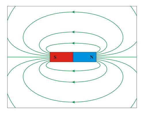
Example of dipole. Magnetic field around a bar magnet.
source: https://commons.wikimedia.org/w/index.php?title=File:DipolMagnet.svg
Units
In the SI system, the unit of magnetic flux is the weber (Wb). If one weber of flux is distributed uniformly across an area of 1m2 perpendicular to the flux, the flux density is clearly one weber per square metre (Wb/m2). This was the unit of magnetic flux density until about 40 years ago, when it was decided that one weber per square meter would henceforth be known as one tesla (T), in honour of Nikola Tesla who is generally credited with inventing the induction motor.
Magnetomotive Force
The ability of the coil to produce flux is quantified in terms of its magnetomotive force (MMF). The MMF of the coil is simply the product of the number of turns (N) and the current (I), and is thus expressed in ampere-turns.
We can make use of an equivalent ‘magnetic Ohm’s law’ by introducing the idea of reluctance (R). The reluctance gives a measure of how difficult it is for the magnetic flux to complete its circuit, in the same way that resistance indicates how much opposition the current encounters in the electric circuit. The magnetic Ohm’s law is
Production of Force
The force on a wire of length l, carrying a current I and exposed to a uniform magnetic flux density B throughout its length is given by the simple expression
F = BIl
where F is in newtons when B is in tesla, I in amperes, and l in metres.
Fleming’s left hand rule
The direction of force can be represented by Fleming’s left hand rule:
- The F (Thumb) represents the direction of Force of the conductor
- The B (Forefinger) represents the direction of the Magnetic field
- The I (Center finger) represents the direction of the Current
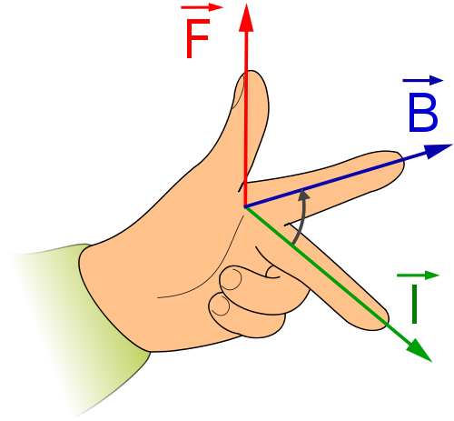 Fleming’s left hand rule
source: https://commons.wikimedia.org/w/index.php?title=File:ManoLaplace.svg


